Patran-specific checks used to calculate element quality for 2D and 3D
elements.
Additional element checks not listed here are not part of the solver’s normal set of
checks, and therefore use HyperMesh check methods.
2D and 3D Element Checks
These checks apply to both types of elements, but when applied to 3D elements they
are generally applied to each face of the element. The value of the worst face is
reported as the 3D element’s overall quality value.
Aspect Ratio (triangle)
The length of a side is divided by the height of the triangle from that
side to its opposite node, then multiplied by ½ of the square root of 3.
In a perfect equilateral triangle, this formula produces a value of 1.
The process is performed for each of the three sides, and the largest
value of the three is reported as the aspect ratio.
Figure 1. Aspect Ratio for Triangles
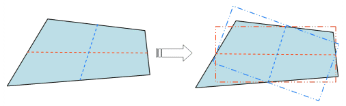
Aspect Ratio (quads)
If the element is not flat, it is projected to a plane which is based on
the average of the element’s corner normals. All subsequent calculations
are based on this projected element rather than the original (curved)
element.
Next, two lines are created which bisect opposite edges of the element.
These lines are typically not perpendicular to each other or to any of
the element edges, but they provide four midpoints.
Third, a rectangle is created for each line, such that the line
perpendicularly bisects two opposing edges of the created rectangle, and
the remaining two edges of the rectangle pass through the remaining
line’s endpoints. This creates two rectangles—one perpendicular to each
line. Figure 2. Aspect Ratio for Quads
Finally, the rectangles are compared to find the one with the greatest
length ratio of longest side to shortest side. This value is reported as
the quad’s aspect ratio. A value of 1 indicates a perfectly equilateral
element, while higher numbers indicate increasingly greater deviation
from equilateral.
Interior Angles
Maximum and minimum values are evaluated independently for triangles and
quadrilaterals.
Jacobian
Deviation of an element from its ideal or "perfect" shape, such as a
triangle’s deviation from equilateral. The Jacobian value ranges from
0.0 to 1.0, where 1.0 represents a perfectly shaped element. The
determinant of the Jacobian relates the local stretching of the
parametric space which is required to fit it onto the global coordinate
space.
HyperWorks evaluates the determinant of the Jacobian
matrix at each of the element’s integration points, also called Gauss
points, or at the element’s corner nodes, and reports the ratio between
the smallest and the largest. In the case of Jacobian evaluation at the
Gauss points, values of 0.7 and above are generally acceptable. You can
select which method of evaluation to use (Gauss point or corner node)
from the Check Element settings.
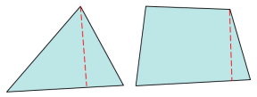
Length (min)
Minimum element lengths are calculated using one of two methods:
The shortest edge of the element. This method is used for
non-tetrahedral 3D elements.
The shortest distance from a corner node to its opposing edge
(or face, in the case of tetra elements); referred to as
"minimal normalized height".
Figure 3. Length (min)
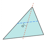
Skew (triangle)
Patran evaluates triangular skew by constructing a line from one of the
triangle’s nodes to the midpoint of its opposite side, and another line
connecting the midpoints of the remaining two sides.
Figure 4. Skew for Triangles
An angle between these created lines is compared to 90 degrees to
find its deviation from square. This process is then repeated for each
of the remaining two nodes, and the largest of the three computed angle
deviations is reported as the element’s skew.
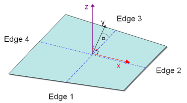
Skew (Quad)
The skew test begins by bisecting the four element edges. This creates
an origin at the vector average of the four corners, with the x-axis
extending from the origin to the bisector on edge 2. Next, finding the
cross-product of the x-axis and the vector that stretches from the
origin to the midpoint of edge 3 defines the z-axis. With the x and z
axes defined, their cross-product defines the y-axis. Figure 5. Skew for Quads
Finally, subtracting the angle α (located between the y axis and
the line bisecting edges 1 and 3) from 90 degrees reveals the element
skew.
Taper
Patran calculates taper by first averaging the corner nodes to find the
element center, and creating lines between this center and the corner
nodes to split the element into four triangles.
The taper calculation is simply the smallest triangle’s area divided by
the average of all the triangle areas—or, put another way, the taper is
quadruple the area of the smallest triangle, divided by the sum of the
areas of all four triangles:
Note: For the sake of display
compatibility, HyperWorks reports an equivalent
value for Taper. Taper is determined as above, but is then
subtracted from 1 to produce a number between zero and one. Thus, as
the element taper decreases, the reported value approaches zero (a
perfect square). Triangles are assigned a value of zero to prevent
them from showing up as failed quads.
Warpage
The warpage test bisects the element edges, creating a point at the
vector average of the element corners. This point serves as the base
node for a plane, with the plane’s x-axis extending from the base node
to the bisector on edge 2 of the element. The plane normal (z-axis) is
in the direction of the cross-product of this x-axis and the vector from
the origin to the bisector of edge 3. Each corner of the quad is then
the same distance, h, from the plane. Next, Patran measures the length
of each half-edge, and calculates the arcsine of the ratio of h to the
shortest half-edge length (L):
3D Element Only Checks
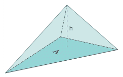
Vol. Aspect Ratio (Tetrahedron)
Patran finds the aspect ratio of Tetra elements by finding the ratio
between a vertex height and ½ the area of the opposing face. This
process is repeated for each vertex, and the largest ratio found. Figure 6. Vol. Aspect Ratio for Tetrahedrons
Next, Patran multiplies the largest ratio found by 0.805927, the
corresponding ratio of an equilateral tetrahedron. The result is
reported as the element’s aspect ratio, with a value of 1 representing a
perfect equilateral tetrahedron.
Vol. Aspect Ratio (pyramid)
Ratio of the element’s longest edge length to its shortest edge
length.
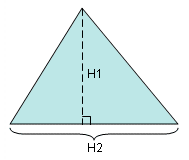
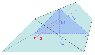
Vol. Aspect Ratio (wedge)
This test begins by averaging the triangular faces of the element to
create a triangular mid-surface. Next, it finds the aspect ratio of the
mid-surface, as for a tria element. Then it compares the average height
(h1) of the wedge element to the mid-surface’s maximum edge length
(h2). Figure 7. Vol. Aspect Ratio for Wedges
If the wedge height h1 exceeds the edge length h2, the wedge’s
aspect ratio equals the mid-surface aspect ratio multiplied by h2, then
divided by the average distance between the triangular faces (h3).
If the wedge height h1 is less than the edge length h2, the wedge aspect
ratio equals either the mid-surface aspect ratio, or the maximum edge
length h2 divided by the average distance between the triangular faces
(h3), whichever is greater.
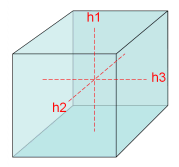
Vol. Aspect Ratio (hexahedron)
Each face of the hex element is treated as a warped quadrilateral, and
its center point found. The volume aspect ratio is simply the ratio of
the largest distance h between the center points of any two opposing
faces, to the smallest such distance.