Many of the methods to check and edit mesh are based around determining mesh quality, but others check for mesh penetration,
detect holes, and locate edges or features.
Use the Normals tool to display and reverse the normals of elements or surfaces. The orientation of element normals can also be adjusted.
The normal of an element is determined by following the order of nodes of the element using the right-hand rule.
The quality of elements in a mesh can be gauged in many ways, and the methods used often depend not only on the element
type, but also on the individual solver used.
HyperWorks includes some alternate methods of calculating certain element types, which only apply to quads or rectangular faces
of solids, and only include alternate checks for Aspect Ratio, Skew, Taper and Warpage.
For the most part, OptiStruct uses the same checks as HyperMesh. However, OptiStruct uses its own method of calculating Aspect Ratio, and it does not support 3D element checks.
Use the Criteria legend to investigate the model via individual criteria, and view a breakdown of all failed and worst
elements based on a set QI range. This is useful when you want to resolve criteria violations, and evaluate the overall
quality of a mesh.
Use the Replicate tool to replicate a mesh from one location to another, with options to keep the original mesh, as
well as to replicate into multiple copies. The replicated elements replace the original elements, maintaining relevant
information like properties, thicknesses, and other solver attributes.
Locally refine 2D elements and attached 1D elements using either the Auto Quads tool, the Box tool, or the Manual tool. These are most useful for aerospace and marine applications, where specific transition patterns are required
from the refined mesh to the existing mesh.
Use the Detach tool to detach elements from the surrounding structure. You can detach elements from a portion of your model so that
it can be translated or moved, or you can offset the new nodes by a specified value. You can also use this panel
to detach and remove elements from your model.
Use the Imprint/Extend tool to extend a mesh to meet another mesh and form a good connection between them, or to imprint overlapping meshes
so that they match one another.
Associate nodes to a point, line, or surface/solid face; move nodes along a surface; place a node at a point on a
surface; remap a list of nodes to a line; or project nodes to an imaginary line passing through two nodes.
Use the Split panel to split plates or solid elements. In addition, hexa elements can also be split using a technique
that moves progressively through a row of elements in the model
Stitch two unconnected meshes by adding elements between them, split elements at weld locations, and combine and split
elements to fix connectivity in the transitional area between fine and coarse mesh areas.
Perform a model-based CAD-CAD, CAD-FE or FE-FE comparison between two models, or two selections of entities, and find
and report geometrical/shape differences.
Rapidly change the shape of the FE mesh without severely sacrificing the mesh quality and create, edit, and apply
shapes for subsequent design optimization studies.
The Design Space environment is dedicated to topology optimization model build and setup. It facilitates rapid model creation by generating
the voxel design space for a number of different use cases.
Many essential utility tools using HyperWorks-Tcl have been developed over the years to support Aerospace customers. A few tools have been collected and upgraded to
be compatible with this release.
Many of the methods to check and edit mesh are based around determining mesh quality, but others check for mesh penetration,
detect holes, and locate edges or features.
The quality of elements in a mesh can be gauged in many ways, and the methods used often depend not only on the element
type, but also on the individual solver used.
Medina-specific checks used to calculate element quality for 2D and 3D
elements.
Additional element checks not listed here are not part of the solver’s normal set of
checks, and therefore use HyperMesh check methods.
2D and 3D Element Checks
These checks apply to both types of elements, but when applied to 3D elements they
are generally applied to each face of the element. The value of the worst face is
reported as the 3D element’s overall quality value.
Aspect Ratio (Edge Ratio)
Edge Ratio is calculated as the ratio between an element’s shortest edge
and its longest edge; For the sake of consistency, HyperWorks inverts this result, effectively making it the
ratio of longest to shortest, and reports the result as the element’s
aspect ratio.
Interior Angles
Maximum and minimum values are evaluated independently for triangles and
quadrilaterals.
Jacobian
Deviation of an element from its ideal or "perfect" shape, such as a
triangle’s deviation from equilateral. The Jacobian value ranges from
0.0 to 1.0, where 1.0 represents a perfectly shaped element. The
determinant of the Jacobian relates the local stretching of the
parametric space which is required to fit it onto the global coordinate
space.
HyperWorks evaluates the determinant of the Jacobian
matrix at each of the element’s integration points, also called Gauss
points, or at the element’s corner nodes, and reports the ratio between
the smallest and the largest. In the case of Jacobian evaluation at the
Gauss points, values of 0.7 and above are generally acceptable. You can
select which method of evaluation to use (Gauss point or corner node)
from the Check Element settings.
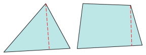
Length (min)
Minimum element lengths are calculated using one of two methods:
The shortest edge of the element. This method is used for
non-tetrahedral 3D elements.
The shortest distance from a corner node to its opposing edge
(or face, in the case of tetra elements); referred to as
"minimal normalized height".
Figure 1. Length (min)
Maximum Angle
Largest angle between adjacent edges of the element is reported.
Minimum Angle
Smallest angle between adjacent edges of the element is reported.
Skew
Element’s interior corner angles are compared to 90 degrees (for quads)
or 60 degrees (for trias). The absolute values of these deviations are
summed and reported.
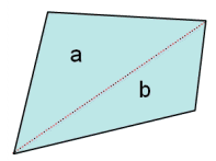
Taper
Quadrilateral elements are split into two triangles. Figure 2. Taper
The area of the smaller of the two triangles is compared to the
total area of the quadrilateral. In Figure 2, .
Note: To improve consistency with other
taper checks, HyperWorks displays a value of 0.5
minus this value so that 0 implies no taper. However, this is not
completely consistent with other taper checks, because in this case
taper ranges from 0 (no taper) to 0.5 (full taper), whereas HyperWorks’s own taper check reports a 1.0 for full
taper.
Warpage
Elements with more than three nodes are split into triangles. The
largest angle between the normals of triangle pairs is reported as the
warpage.
3D Element Only Checks
Medina does not use any 3D specific checks. HyperWorks uses its own
checks instead.