HyperWorks CFD includes some alternate methods of calculating certain
element types, which only apply to quads or rectangular faces of solids, and only include
alternate checks for Aspect Ratio, Skew, Taper and Warpage.
Note: Because these methods apply only to certain quality checks, in order to use
them you must choose the set individually option in the
Check Element settings.
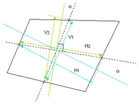
Aspect Ratio
ratio1 = V1/H1
ratio2 = V2/H2
Skew value is larger of ratio1 or ratio2. Figure 1. Aspect Ratio
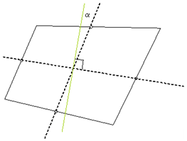
Skew
First, HyperWorks CFD constructs lines connecting the
midpoints of each edge of the quad, dotted in the picture below. Next,
HyperWorks CFD constructs a third line, green in the
picture below, perpendicular to one of the initial lines, then finds the
angle between this third line and the remaining initial line – with
which is it most likely not perpendicular, unless the quad is a perfect
rectangle.
α is the skew (angle) value. Figure 2. Skew
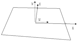
Taper
First, the quad’s nodes are projected to plane defined by the
orthonormal vectors U-V found as follows:
Z = X × Y
V = Z × X
U = X
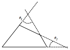
Figure 3. Figure 4.
In HyperWorks CFD, Taper angle is defined as: .
The optimal value is 0°, and a generally acceptable limit is. <= 30°.
The The ultimate limit, which the Taper angle cannot exceed is 45°.
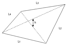
Warpage
Only applies to quads or rectangular faces of solids. Figure 5.
Warpage = 100 * h / max { Li }, where h is the minimum distance
between the diagonals.