The quality of elements in a mesh can be gauged in many ways, and the methods used
often depend not only on the element type, but also on the individual solver
used.
When possible, the most common or standard methods are used, but there is no truly
standardized set of element quality checks. When a solver does not support a specific
check within HyperMesh, HyperMesh uses its own
method to perform the check.
HyperMesh
When possible, HyperMesh checks strive to maintain compatibility
with popular solvers.
2D and 3D Element Checks
The following checks apply to both types of elements, but when applied to 3D elements
they are generally applied to each face of the element. The value of the worst face
is reported as the 3D element’s overall quality value.
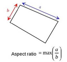
Aspect Ratio
Ratio of the longest edge of an element to either its shortest edge or
the shortest distance from a corner node to the opposing edge ("minimal
normalized height"). HyperMesh uses the same method
used for the Length (min) check.
For 3D elements, each face of the element is treated as a 2D element and
its aspect ratio determined. The largest aspect ratio among these faces
is returned as the 3D element’s aspect ratio.
Aspect ratios should rarely exceed 5:1
Chordal Deviation
Largest distance between the centers of element edges and the associated
surface.
Second order elements return the same chordal deviation as first order,
when the corner nodes are used due to the expensive nature of the
calculations. Figure 1. Chordal Deviation
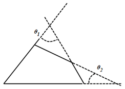
Interior Angles
Maximum and minimum interior angles are evaluated independently for
triangles and quadrilaterals.
Jacobian
Deviation of an element from its ideal or "perfect" shape, such as a
triangle’s deviation from equilateral.
The Jacobian value ranges from 0.0 to 1.0, where 1.0 represents a
perfectly shaped element. The determinant of the Jacobian relates the
local stretching of the parametric space which is required to fit it
onto the global coordinate space.
HyperMesh evaluates the determinant of the Jacobian
matrix at each of the element’s integration points (also called Gauss
points) or at the element’s corner nodes, and reports the ratio between
the smallest and the largest. In the case of Jacobian evaluation at the
Gauss points, values of 0.7 and above are generally acceptable. You can
select which method of evaluation to use (Gauss point or corner node)
from the Check Element settings.
Length (min)
Minimum element lengths are calculated using one of two methods.
The shortest edge of the element. This method is used for
non-tetrahedral 3D elements.
The shortest distance from a corner node to its opposing edge
(or face, in the case of tetra elements); referred to as
"minimal normalized height".
Figure 2. Length Check
You can choose which method to use in the Check Element
settings.
Note: This setting affects the calculation
of the Aspect Ratio check.
Minimum Length / Size
Minimum element size is calculated using:
Shortest edge
Length of the shortest edge of each element is used.
Minimal normalized height
Is a more accurate, but more complex height.
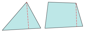
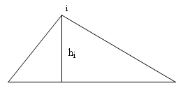
For triangular elements, for each corner node (i), HyperMesh calculates the closest
(perpendicular) distance to the ray including the opposite
leg of the triangle, h(i). MNH = min(hi) * 2/sqrt(3.0). The
scaling factor 2/sqrt(3.0) ensures that for equilateral
triangles, the MNH is the length of the minimum side. Figure 3. Minimal Normalized Height for Triangular
Elements
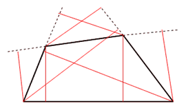
For quadrilateral elements, for each corner node, HyperMesh calculates the closest
(perpendicular) distances to the rays containing the legs of
the quadrilateral that do not include this node. The figure
above depicts these lengths as red lines. Minimal normalized
height is taken to be the minimum of all eight lines and the
four edge lengths, thus, the minimum of 12 possible
lengths. Figure 4. Minimal Normalized Height for Quadrilateral
Elements
Minimal height
The same as minimal normalized height, but without a scaling
factor.
Skew
Skew of triangular elements is calculated by finding the minimum angle
between the vector from each node to the opposing mid-side, and the
vector between the two adjacent mid-sides at each node of the
element. Figure 5. Skew of Triangular Elements
The minimum angle found is subtracted from ninety degrees and
reported as the element’s skew.
Note: Skew for quads is part of the
HyperMesh-Alt
quality check.
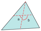
Taper
Taper ratio for the quadrilateral element is defined by first finding
the area of the triangle formed at each corner grid point. Figure 6. Taper for Quadrilateral Element
These areas are then compared to one half of the area of the
quadrilateral.
HyperMesh then finds the smallest ratio of each of
these triangular areas to ½ the quad element’s total area (in the
diagram above, "a" is smallest). The resulting value is subtracted from
1, and the result reported as the element taper. This means that as the
taper approaches 0, the shape approaches a rectangle.
Triangles are assigned a value of 0, in order to prevent HyperMesh from mistaking them for highly-tapered
quadrilaterals and reporting them as "failed".
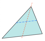
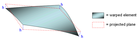
Warpage
Amount by which an element, or in the case of solid elements, an element
face, deviates from being planar. Since three points define a plane,
this check only applies to quads. The quad is divided into two trias
along its diagonal, and the angle between the trias’ normals is
measured.
Warpage of up to five degrees is generally acceptable. Figure 7. Warpage
3D Element Only Checks
Minimum Length / Size
Two methods are used to calculate the minimum element size.
Shortest edge
Length of the shortest edge of each element is used.
Minimal normalized height
More accurate, but more complex.
HyperMesh calculates the closest
(perpendicular) distances to the planes formed by the
opposite faces for each corner node. Figure 8.
The resulting minimum length/size is the minimum of all such measured
distances.
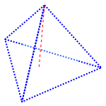
Tetra Collapse
The height of the tetra element is measured from each of the four nodes
to its opposite face, and then divided by the square root of the face’s
area. Figure 9.
The minimum of the four resulting values (one per node) is then
normalized by dividing it by 1.24. As the tetra collapses, the value
approaches 0.0, while a perfect tetra has a value of 1.0.
Non-tetrahedral elements are given values of 1 so that HyperMesh will not mistake them for bad tetra
elements.
Vol. Aspect Ratio
Tetrahedral elements are evaluated by finding the longest edge length
and dividing it by the shortest height (measured from a node to its
opposing face). Other 3D elements, such as hex elements, are evaluated
based on the ratio of their longest edge to their shortest edge.
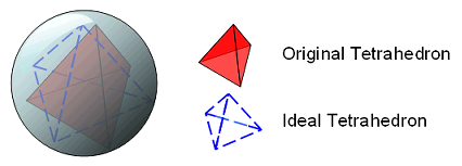
Volume Skew
Only applicable to tetrahedral elements; all others are assigned values
of zero. Volume Skew is defined as 1-shape factor, so a skew of 0 is
perfect and a skew of 1 is the worst possible value.
The shape factor for a tetrahedral element is determined by dividing the
element’s volume by the volume of an ideal (equilateral) tetrahedron of
the same circumradius. In the case of tetrahedral elements, the
circumradius is the radius of a sphere passing through the four vertices
of the tetrahedron. Figure 10.
HyperMesh-Alt
HyperMesh includes some alternate methods of calculating certain
element types, which only apply to quads or rectangular faces of solids, and only include
alternate checks for Aspect Ratio, Skew, Taper and Warpage.
Note: Because these methods apply only to certain quality checks, in order to use
them you must choose the set individually option in the
Check Element settings.
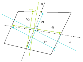
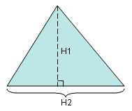
Aspect Ratio
ratio1 = V1/H1
ratio2 = V2/H2
Skew value is larger of ratio1 or ratio2. Figure 11. Aspect Ratio
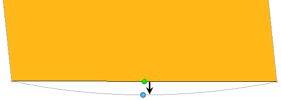
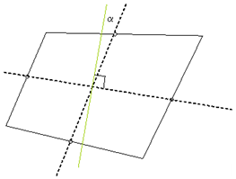
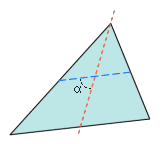
Skew
First, HyperMesh constructs lines connecting the
midpoints of each edge of the quad, dotted in the picture below. Next,
HyperMesh constructs a third line, green in the
picture below, perpendicular to one of the initial lines, then finds the
angle between this third line and the remaining initial line – with
which is it most likely not perpendicular, unless the quad is a perfect
rectangle.
α is the skew (angle) value. Figure 12. Skew
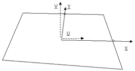
Taper
First, the quad’s nodes are projected to plane defined by the
orthonormal vectors U-V found as follows:
Z = X × Y
V = Z × X
U = X
Figure 13. Figure 14.
In HyperMesh, Taper angle is defined as: .
The optimal value is 0°, and a generally acceptable limit is. <= 30°.
The The ultimate limit, which the Taper angle cannot exceed is 45°.
Warpage
Only applies to quads or rectangular faces of solids. Figure 15.
Warpage = 100 * h / max { Li }, where h is the minimum distance
between the diagonals.
OptiStruct
For the most part, OptiStruct uses the same checks as
HyperMesh. However, OptiStruct
uses its own method of calculating Aspect Ratio, and it does not support 3D element
checks.
Aspect Ratio
Ratio between the minimum and maximum side lengths.
3D elements are evaluated by treating each face of the element as a 2D
element, finding the aspect ratio of each face, and then returning the
most extreme aspect ratio found.
Chordal Deviation
Chordal deviation of an element is calculated as the largest distance
between the centers of element edges and the associated surface. 2nd
order elements return the same chordal deviation as 1st order, when the
corner nodes are used due to the expensive nature of the
calculations. Figure 16. Chordal Deviation
Interior Angles
Maximum and minimum values are evaluated independently for triangles and
quadrilaterals.
Jacobian
Deviation of an element from its ideal or "perfect" shape, such as a
triangle’s deviation from equilateral. The Jacobian value ranges from
0.0 to 1.0, where 1.0 represents a perfectly shaped element. The
determinant of the Jacobian relates the local stretching of the
parametric space which is required to fit it onto the global coordinate
space.
HyperMesh evaluates the determinant of the Jacobian
matrix at each of the element’s integration points, also called Gauss
points, or at the element’s corner nodes, and reports the ratio between
the smallest and the largest. In the case of Jacobian evaluation at the
Gauss points, values of 0.7 and above are generally acceptable. You can
select which method of evaluation to use, Gauss point or corner node,
from the Check Element settings.
Length (min)
Minimum element lengths are calculated using one of two methods:
The shortest edge of the element. This method is used for
non-tetrahedral 3D elements.
The shortest distance from a corner node to its opposing edge
(or face, in the case of tetra elements); referred to as
"minimal normalized height".
Figure 17. Length (Min)
Skew
Skew of triangular elements is calculated by finding the minimum angle
between the vector from each node to the opposing mid-side, and the
vector between the two adjacent mid-sides at each node of the
element. Figure 18. Skew of Triangular Element
The minimum angle found is subtracted from ninety degrees and
reported as its skew.
Warpage
Amount by which an element, or in the case of solid elements, an element
face, deviates from being planar. Since three points define a plane,
this check only applies to quads. The quad is divided into two trias
along its diagonal, and the angle between the trias’ normals is
measured.
Warpage of up to five degrees is generally acceptable. Figure 19. Warpage
Abaqus
Abaqus-specific checks used to calculate element quality
for 2D and 3D elements.
2D and 3D Element Checks
These checks apply to both types of elements, but when applied to 3D elements they
are generally applied to each face of the element. The value of the worst face is
reported as the 3D element’s overall quality value.
Additional element checks not listed here are not part of the solver’s normal set of
checks, and therefore use HyperMesh check methods.
Aspect Ratio
Ratio of the longest edge of an element to its shortest edge.
When applied to 3D elements, the same method is used (longest edge
divided by shortest edge) rather than evaluating each face individually
and taking the worst face result.
Interior Angles
Maximum and minimum values are evaluated independently for triangles and
quadrilaterals.
Jacobian
Deviation of an element from its ideal or "perfect" shape, such as a
triangle’s deviation from equilateral. The Jacobian value ranges from
0.0 to 1.0, where 1.0 represents a perfectly shaped element. The
determinant of the Jacobian relates the local stretching of the
parametric space which is required to fit it onto the global coordinate
space.
HyperMesh evaluates the determinant of the Jacobian
matrix at each of the element’s integration points, also called Gauss
points, or at the element’s corner nodes, and reports the ratio between
the smallest and the largest. In the case of Jacobian evaluation at the
Gauss points, values of 0.7 and above are generally acceptable. You can
select which method of evaluation to use (Gauss point or corner node)
from the Check Element settings.
Length (min)
Minimum element lengths are calculated using one of two methods:
The shortest edge of the element. This method is used for
non-tetrahedral 3D elements.
The shortest distance from a corner node to its opposing edge
(or face, in the case of tetra elements); referred to as
"minimal normalized height".
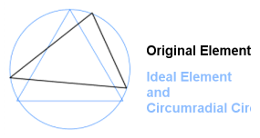
Skew (tria only)
Defined by shape factor. Abaqus determines triangular element shape
factor by dividing the element’s area by the area of an ideally shaped
element. The ideally shaped element is defined as an equilateral
triangle with the same circumradius—the radius of a circle that passes
through the three vertices of the triangle—as the element. Figure 20.
This shape factor converts to skew by subtracting it from 1. Thus, a
perfect equilateral tria element has a skew of 0 and the worst tria has
a value of 1.0.
Quadrilaterals are simply assigned a value of 0.
3D Element Only Checks
Volume Skew
Only applicable to tetrahedral elements; all others are assigned values
of zero.
Volume Skew is defined as 1 minus the shape factor, so a skew of 0 is
perfect and a skew of 1 is the worst possible value.
The shape factor for a tetrahedral element is determined by dividing the
element’s volume by the volume of an ideal (equilateral) tetrahedron of
the same circumradius. In the case of tetrahedral elements, the
circumradius is the radius of a sphere passing through the four vertices
of the tetrahedron. Figure 21. Volume Skew
ANSYS
ANSYS-specific checks used to calculate element quality
for 2D and 3D elements.
2D and 3D Element Checks
These checks apply to both types of elements, but when applied to 3D elements they
are generally applied to each face of the element. The value of the worst face is
reported as the 3D element’s overall quality value.
Additional element checks not listed here are not part of the solver’s normal set of
checks, and therefore use HyperMesh check methods.
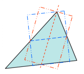
Aspect Ratio (tria)
For tria elements, a line is drawn from one node to the midpoint of the
opposite edge. Next, another line is drawn between the midpoints of the
remaining two sides. These lines are typically not perpendicular to each
other or to any of the element edges, but provide four points (three
midpoints plus the vertex). Figure 22.
Then, a rectangle is created for each of these two lines, such that one
line perpendicularly meets the midpoints of two opposing edges of the
rectangle, and the remaining edges of the rectangle pass through the end
points of the remaining line. This results in two rectangles, one
perpendicular to each of the two lines. Figure 23.
Third, this process is repeated for each of the remaining two nodes of
the tria element, resulting in the construction of four additional
rectangles (six in total).
Finally, each rectangle is examined to find the ratio of its longest
side to its shortest side. Of these six values—one for each
rectangle—the most extreme value is then divided by the square root of
three to produce the tria aspect ratio.
The best aspect ratio (an equilateral tria) is 1. Higher numbers
indicate greater deviation from equilateral.
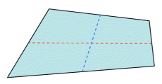
Aspect Ratio (quad)
If the element is not flat, it’s projected to a plane which is based on
the average of the element’s corner normals. All subsequent calculations
are based on this projected element rather than the original (curved)
element.
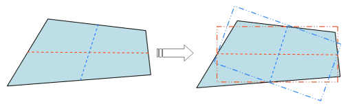
Next, two lines are created which bisect opposite edges of the element.
These lines are typically not perpendicular to each other or to any of
the element edges, but they provide four midpoints. Figure 24.
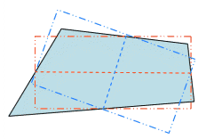
Third, a rectangle is created for each line, such that the line
perpendicularly bisects two opposing edges of the created rectangle, and
the remaining two edges of the rectangle pass through the remaining
line’s endpoints. This creates two rectangles—one perpendicular to each
line. Figure 25.
Finally, the rectangles are compared to find the one with the greatest
length ratio of longest side to shortest side. This value is reported as
the quad’s aspect ratio. A value of one indicates a perfectly
equilateral element, while higher numbers indicate increasingly greater
deviation from equilateral.
Interior Angles
Maximum and minimum values are evaluated independently for triangles and
quadrilaterals.
Jacobian
Deviation of an element from its ideal or "perfect" shape, such as a
triangle’s deviation from equilateral. The Jacobian value ranges from
0.0 to 1.0, where 1.0 represents a perfectly shaped element. The
determinant of the Jacobian relates the local stretching of the
parametric space which is required to fit it onto the global coordinate
space.
HyperMesh evaluates the determinant of the Jacobian
matrix at each of the element’s integration points, also called Gauss
points, or at the element’s corner nodes, and reports the ratio between
the smallest and the largest. In the case of Jacobian evaluation at the
Gauss points, values of 0.7 and above are generally acceptable. You can
select which method of evaluation to use (Gauss point or corner node)
from the Check Element settings.
Length (min)
Minimum element lengths are calculated using one of two methods:
The shortest edge of the element. This method is used for
non-tetrahedral 3D elements.
The shortest distance from a corner node to its opposing edge
(or face, in the case of tetra elements); referred to as
"minimal normalized height".
Figure 26.
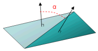
Angle Deviation (Skew)
Only applicable to quadrilateral elements, and relies upon the angles
between adjacent legs at each corner node (that is, the interior angles
at each corner). Each angle is compared to a base of 90 degrees, and the
one with the largest deviation from 90 is reported as the angle
deviation. Triangular elements are given a value of zero.
Warping Factor
Only applicable to quadrilateral elements as well as the quadrilateral
faces of 3D bricks, wedges, and pyramids.
Calculated by creating a normal from the vector product of the element’s
two diagonals. Next, the element’s area is projected to a plane through
the average normal. Finally, the difference in height is measured
between each node of the original element and its corresponding node on
the projection. For flat elements, this is always zero, but for warped
elements one or more nodes will deviate from the plane. The greater the
difference, the more warped the element is. Figure 27.
The warping factor is calculated as the edge height difference divided
by the square root of the projected area.
3D Element Only Checks
ANSYS does not use any exclusively 3D checks within
HyperMesh, but HyperMesh does use its own
when ANSYS is set as the solver. For details on 3D
checks, refer to HyperMesh.
I-deas
I-deas-specific checks used to calculate element quality
for 2D and 3D elements.
Additional element checks not listed here are not part of the solver’s normal set of
checks, and therefore use HyperMesh check methods.
2D and 3D Element Checks
These checks apply to both types of elements, but when applied to 3D elements they
are generally applied to each face of the element. The value of the worst face is
reported as the 3D element’s overall quality value.
Stretch (Aspect Ratio)
Stretch is evaluated differently depending on whether the element is
triangular or quadrilateral:
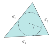
For trias, the radius of the largest circle that fits within the
element is divided by the longest edge, then multiplied by the
square root of 12. Figure 28. Stretch for Trias
For quads, the minimum edge length is divided by the maximum
diagonal length. The result is multiplied by the square root of
2.
Note: The inverse of stretch displays on-screen in HyperMesh as the aspect.
Chordal Deviation
Largest distance between the centers of element edges and the associated
surface. Second order elements return the same chordal deviation as
first order, when the corner nodes are used due to the expensive nature
of the calculations. Figure 29. Chordal Deviation
Jacobian
Deviation of an element from its ideal or "perfect" shape, such as a
triangle’s deviation from equilateral. The Jacobian value ranges from
0.0 to 1.0, where 1.0 represents a perfectly shaped element. The
determinant of the Jacobian relates the local stretching of the
parametric space which is required to fit it onto the global coordinate
space.
HyperMesh evaluates the determinant of the Jacobian
matrix at each of the element’s integration points, also called Gauss
points, or at the element’s corner nodes, and reports the ratio between
the smallest and the largest. In the case of Jacobian evaluation at the
Gauss points, values of 0.7 and above are generally acceptable. You can
select which method of evaluation to use (Gauss point or corner node)
from the Check Element settings.
Length (min)
Minimum element lengths are calculated using one of two methods:
The shortest edge of the element. This method is used for
non-tetrahedral 3D elements.
The shortest distance from a corner node to its opposing edge
(or face, in the case of tetra elements); referred to as
"minimal normalized height".
Figure 30. Length (min)
Skew
Deviation of an element’s corners from 90 degrees (for quads) or 60
degrees (for trias).
The check calculates skew by finding:
for quadrilaterals
for triangular elements
Where alpha is the angle of each corner. An ideal/equilateral
element has a skew of zero, as none of its corners deviate from the
target (90 or 60 degrees).
Taper
Taper ratio for the quadrilateral element is defined by first finding
the area of the triangle formed at each corner grid point. Figure 31. Taper
These areas are then compared to one half of the area of the
quadrilateral.
HyperMesh then finds the smallest ratio of each of
these triangular areas to ½ the quad element’s total area. In the
diagram above, "a" is smallest. The resulting value is subtracted from
1, and the result reported as the element taper. This means that as the
taper approaches 0, the shape approaches a rectangle.Triangles are assigned a value of 0, in
order to prevent HyperMesh from mistaking them for
highly-tapered quadrilaterals and reporting them as "failed".
Warpage
The amount by which an element, or in the case of solid elements, an
element face, deviates from being planar. Since three points define a
plane, this check only applies to quads. The quad is divided into two
trias along its diagonal, and the angle between the trias’ normals is
measured.
3D Element Only Checks
Stretch (volume aspect ratio)
Stretch is evaluated differently depending on whether the element is a
tetrahedron, Wedge, Brick, or Pyramid.
Tetras
The radius of the largest sphere that fits within the
element is divided by the longest edge. This value is then
multiplied by the square root of 24.
Wedges
Each face is evaluated for its 2D stretch, and the worst
value is reported. This means that the value reported for
vol AR should always be the same as that reported for
aspect.
Bricks
The minimum edge length is divided by the maximum diagonal
length. The result is multiplied by the square root of
3.
Pyramids
No check is defined, so HyperMesh performs
its standard check in which each face is evaluated as a 2D
object and the worst result reported.
Medina
Medina-specific checks used to calculate element quality for 2D and 3D
elements.
Additional element checks not listed here are not part of the solver’s normal set of
checks, and therefore use HyperMesh check methods.
2D and 3D Element Checks
These checks apply to both types of elements, but when applied to 3D elements they
are generally applied to each face of the element. The value of the worst face is
reported as the 3D element’s overall quality value.
Aspect Ratio (Edge Ratio)
Edge Ratio is calculated as the ratio between an element’s shortest edge
and its longest edge; For the sake of consistency, HyperMesh inverts this result, effectively making it the
ratio of longest to shortest, and reports the result as the element’s
aspect ratio.
Interior Angles
Maximum and minimum values are evaluated independently for triangles and
quadrilaterals.
Jacobian
Deviation of an element from its ideal or "perfect" shape, such as a
triangle’s deviation from equilateral. The Jacobian value ranges from
0.0 to 1.0, where 1.0 represents a perfectly shaped element. The
determinant of the Jacobian relates the local stretching of the
parametric space which is required to fit it onto the global coordinate
space.
HyperMesh evaluates the determinant of the Jacobian
matrix at each of the element’s integration points, also called Gauss
points, or at the element’s corner nodes, and reports the ratio between
the smallest and the largest. In the case of Jacobian evaluation at the
Gauss points, values of 0.7 and above are generally acceptable. You can
select which method of evaluation to use (Gauss point or corner node)
from the Check Element settings.
Length (min)
Minimum element lengths are calculated using one of two methods:
The shortest edge of the element. This method is used for
non-tetrahedral 3D elements.
The shortest distance from a corner node to its opposing edge
(or face, in the case of tetra elements); referred to as
"minimal normalized height".
Figure 32. Length (min)
Maximum Angle
Largest angle between adjacent edges of the element is reported.
Minimum Angle
Smallest angle between adjacent edges of the element is reported.
Skew
Element’s interior corner angles are compared to 90 degrees (for quads)
or 60 degrees (for trias). The absolute values of these deviations are
summed and reported.
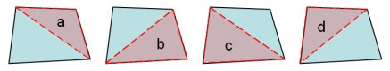
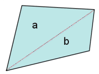
Taper
Quadrilateral elements are split into two triangles. Figure 33. Taper
The area of the smaller of the two triangles is compared to the
total area of the quadrilateral. In Figure 33, .
Note: To improve consistency with other
taper checks, HyperMesh displays a value of 0.5
minus this value so that 0 implies no taper. However, this is not
completely consistent with other taper checks, because in this case
taper ranges from 0 (no taper) to 0.5 (full taper), whereas HyperMesh’s own taper check reports a 1.0 for full
taper.
Warpage
Elements with more than three nodes are split into triangles. The
largest angle between the normals of triangle pairs is reported as the
warpage.
3D Element Only Checks
Medina does not use any 3D specific checks. HyperMesh uses its own
checks instead.
Moldflow
Moldflow-specific checks used to calculate element quality for 2D and 3D
elements.
Additional element checks not listed here are not part of the solver’s normal set of
checks, and therefore use HyperMesh check methods.
2D and 3D Element Checks
These checks apply to both types of elements, but when applied to 3D elements they
are generally applied to each face of the element. The value of the worst face is
reported as the 3D element’s overall quality value.
Aspect Ratio
Only applied to triangles, with quadrilaterals given a value
of:
This is the same value obtained from an equilateral triangle, and is
assigned to quads to prevent HyperMesh from
misinterpreting a quad as a badly formed triangular element.
MoldFlow calculates a triangle’s aspect ratio by squaring the longest
edge of the triangle, and dividing the result by twice the triangle’s
area. 1.0 denotes a perfect equilateral triangle.
When applied to 3D elements, the aspect ratio is the ratio between the
longest and shortest edges of the tetrahedral element.
3D Element Only Checks
Vol. Aspect Ratio
Finds the perpendicular height h of each node, and then dividing the
longest edge length L by the shortest height h and multiplying by the
square root of 1.5:This results in an equilateral tetrahedron
having a volume aspect ratio of 1.5. Non-tetrahedral elements are
assigned a value of 1.0.
Nastran
Nastran-specific checks used to calculate element quality
for 2D and 3D elements.
Additional element checks not listed here are not part of the solver’s normal set of
checks, and therefore use HyperMesh check methods.
2D and 3D Element Checks
Aspect Ratio
Ratio of the longest edge of an element to its shortest edge. Figure 34.
Interior Angles
Maximum and minimum values are evaluated independently for triangles and
quadrilaterals.
Jacobian
Deviation of an element from its ideal or "perfect" shape, such as a
triangle’s deviation from equilateral. The Jacobian value ranges from
0.0 to 1.0, where 1.0 represents a perfectly shaped element. The
determinant of the Jacobian relates the local stretching of the
parametric space which is required to fit it onto the global coordinate
space.
HyperMesh evaluates the determinant of the Jacobian
matrix at each of the element’s integration points, also called Gauss
points, or at the element’s corner nodes, and reports the ratio between
the smallest and the largest. In the case of Jacobian evaluation at the
Gauss points, values of 0.7 and above are generally acceptable. You can
select which method of evaluation to use (Gauss point or corner node)
from the Check Element settings.
Skew
HyperMesh creates lines between the midpoints of
opposite sides of the element, then measures the angles between these
lines. The angle with the greatest deviation from the ideal value is
used to determine skew.
Taper
HyperMesh finds the taper of quadrilateral elements by
treating each node as the corner of a triangle, using one of the quad’s
diagonals as the triangle’s third leg. The areas of each of these four
"virtual" triangles are compared to one half of the total area of the
quadrilateral element to produce a ratio; the largest of these ratios is
then compared to the tolerance value. A value of 1.0 is a perfect
quadrilateral, and higher numbers denote greater taper.
However, for the sake of consistency within HyperMesh,
an equivalent taper is reported instead. This means that the smallest
area ratio found (instead of the largest ratio) is subtracted from 1, so
that 0 represents a perfect quadrilateral element instead of 1.0, and
greater deviation from 0 indicates greater taper. Triangle elements are
simply assigned a value of 0 to prevent HyperMesh from
incorrectly identifying them as failed (highly-tapered) quads.
Warpage
First, HyperMesh constructs a plane based on the mean
of the quad’s four points. This means that the corner points of a warped
quad are alternately H units above and below the constructed plane. This
value is then used along with the length of the element’s diagonals in
the following equation:Where WC is the Warping Coefficient, H is
the "height" or distance of the nodes from the constructed plane, and D1
and D2 are the lengths of the diagonals. Thus, a perfect quad has a WC
of zero.
3D Element Only Checks
Vol. Aspect Ratio
HyperMesh evaluates Tetrahedral elements by finding
the longest edge length and dividing it by the shortest height, measured
from a node to its opposing face. Other 3D elements, such as hex
elements, are evaluated based on the ratio of their longest edge to
their shortest edge.
Warpage
HyperMesh evaluates warpage on solid element faces by
dividing the quad face into two trias along its diagonal, and measuring
the cosine of the angle between the trias’ normals. This value will be
1.0 for a face where all nodes lie on the same plane.
Patran
Patran-specific checks used to calculate element quality for 2D and 3D
elements.
Additional element checks not listed here are not part of the solver’s normal set of
checks, and therefore use HyperMesh check methods.
2D and 3D Element Checks
These checks apply to both types of elements, but when applied to 3D elements they
are generally applied to each face of the element. The value of the worst face is
reported as the 3D element’s overall quality value.
Aspect Ratio (triangle)
The length of a side is divided by the height of the triangle from that
side to its opposite node, then multiplied by ½ of the square root of 3.
In a perfect equilateral triangle, this formula produces a value of 1.
The process is performed for each of the three sides, and the largest
value of the three is reported as the aspect ratio. Figure 35. Aspect Ratio for Triangles
Aspect Ratio (quads)
If the element is not flat, it is projected to a plane which is based on
the average of the element’s corner normals. All subsequent calculations
are based on this projected element rather than the original (curved)
element.
Next, two lines are created which bisect opposite edges of the element.
These lines are typically not perpendicular to each other or to any of
the element edges, but they provide four midpoints.
Third, a rectangle is created for each line, such that the line
perpendicularly bisects two opposing edges of the created rectangle, and
the remaining two edges of the rectangle pass through the remaining
line’s endpoints. This creates two rectangles—one perpendicular to each
line. Figure 36. Aspect Ratio for Quads
Finally, the rectangles are compared to find the one with the greatest
length ratio of longest side to shortest side. This value is reported as
the quad’s aspect ratio. A value of 1 indicates a perfectly equilateral
element, while higher numbers indicate increasingly greater deviation
from equilateral.
Interior Angles
Maximum and minimum values are evaluated independently for triangles and
quadrilaterals.
Jacobian
Deviation of an element from its ideal or "perfect" shape, such as a
triangle’s deviation from equilateral. The Jacobian value ranges from
0.0 to 1.0, where 1.0 represents a perfectly shaped element. The
determinant of the Jacobian relates the local stretching of the
parametric space which is required to fit it onto the global coordinate
space.
HyperMesh evaluates the determinant of the Jacobian
matrix at each of the element’s integration points, also called Gauss
points, or at the element’s corner nodes, and reports the ratio between
the smallest and the largest. In the case of Jacobian evaluation at the
Gauss points, values of 0.7 and above are generally acceptable. You can
select which method of evaluation to use (Gauss point or corner node)
from the Check Element settings.
Length (min)
Minimum element lengths are calculated using one of two methods:
The shortest edge of the element. This method is used for
non-tetrahedral 3D elements.
The shortest distance from a corner node to its opposing edge
(or face, in the case of tetra elements); referred to as
"minimal normalized height".
Figure 37. Length (min)
Skew (triangle)
Patran evaluates triangular skew by constructing a line from one of the
triangle’s nodes to the midpoint of its opposite side, and another line
connecting the midpoints of the remaining two sides.
Figure 38. Skew for Triangles
An angle between these created lines is compared to 90 degrees to
find its deviation from square. This process is then repeated for each
of the remaining two nodes, and the largest of the three computed angle
deviations is reported as the element’s skew.
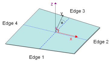
Skew (Quad)
The skew test begins by bisecting the four element edges. This creates
an origin at the vector average of the four corners, with the x-axis
extending from the origin to the bisector on edge 2. Next, finding the
cross-product of the x-axis and the vector that stretches from the
origin to the midpoint of edge 3 defines the z-axis. With the x and z
axes defined, their cross-product defines the y-axis. Figure 39. Skew for Quads
Finally, subtracting the angle α (located between the y axis and
the line bisecting edges 1 and 3) from 90 degrees reveals the element
skew.
Taper
Patran calculates taper by first averaging the corner nodes to find the
element center, and creating lines between this center and the corner
nodes to split the element into four triangles.
The taper calculation is simply the smallest triangle’s area divided by
the average of all the triangle areas—or, put another way, the taper is
quadruple the area of the smallest triangle, divided by the sum of the
areas of all four triangles:
Note: For the sake of display
compatibility, HyperMesh reports an equivalent
value for Taper. Taper is determined as above, but is then
subtracted from 1 to produce a number between zero and one. Thus, as
the element taper decreases, the reported value approaches zero (a
perfect square). Triangles are assigned a value of zero to prevent
them from showing up as failed quads.
Warpage
The warpage test bisects the element edges, creating a point at the
vector average of the element corners. This point serves as the base
node for a plane, with the plane’s x-axis extending from the base node
to the bisector on edge 2 of the element. The plane normal (z-axis) is
in the direction of the cross-product of this x-axis and the vector from
the origin to the bisector of edge 3. Each corner of the quad is then
the same distance, h, from the plane. Next, Patran measures the length
of each half-edge, and calculates the arcsine of the ratio of h to the
shortest half-edge length (L):
3D Element Only Checks
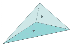
Vol. Aspect Ratio (Tetrahedron)
Patran finds the aspect ratio of Tetra elements by finding the ratio
between a vertex height and ½ the area of the opposing face. This
process is repeated for each vertex, and the largest ratio found. Figure 40. Vol. Aspect Ratio for Tetrahedrons
Next, Patran multiplies the largest ratio found by 0.805927, the
corresponding ratio of an equilateral tetrahedron. The result is
reported as the element’s aspect ratio, with a value of 1 representing a
perfect equilateral tetrahedron.
Vol. Aspect Ratio (pyramid)
Ratio of the element’s longest edge length to its shortest edge
length.
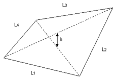
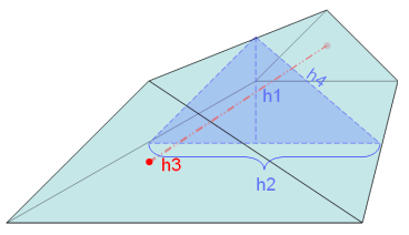
Vol. Aspect Ratio (wedge)
This test begins by averaging the triangular faces of the element to
create a triangular mid-surface. Next, it finds the aspect ratio of the
mid-surface, as for a tria element. Then it compares the average height
(h1) of the wedge element to the mid-surface’s maximum edge length
(h2). Figure 41. Vol. Aspect Ratio for Wedges
If the wedge height h1 exceeds the edge length h2, the wedge’s
aspect ratio equals the mid-surface aspect ratio multiplied by h2, then
divided by the average distance between the triangular faces (h3).
If the wedge height h1 is less than the edge length h2, the wedge aspect
ratio equals either the mid-surface aspect ratio, or the maximum edge
length h2 divided by the average distance between the triangular faces
(h3), whichever is greater.
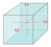
Vol. Aspect Ratio (hexahedron)
Each face of the hex element is treated as a warped quadrilateral, and
its center point found. The volume aspect ratio is simply the ratio of
the largest distance h between the center points of any two opposing
faces, to the smallest such distance. Figure 42. Vol. Aspect Ratio for Hexahedrons